

25Q64FV Datasheet – 64M-bit Serial Flash memory (W25Q64FV)
25Q64FV overview
The W25Q64FV (64M-bit) Serial Flash memory provides a storage solution for systems with limited space, pins and power. The 25Q series offers flexibility and performance well beyond ordinary Serial Flash devices. They are ideal for code shadowing to RAM, executing code directly from Dual/Quad SPI (XIP) and storing voice, text and data. The device operates on a single 2.7V to 3.6V power supply with current consumption as low as 4mA active and 1µA for power-down. All devices are offered in space-saving packages.
The W25Q64FV array is organized into 32,768 programmable pages of 256-bytes each. Up to 256 bytes can be programmed at a time. Pages can be erased in groups of 16 (4KB sector erase), groups of 128 (32KB block erase), groups of 256 (64KB block erase) or the entire chip (chip erase). The W25Q64FV has 2,048 erasable sectors and 128 erasable blocks respectively. The small 4KB sectors allow for greater flexibility in applications that require data and parameter storage. (See figure 2.)
The W25Q64FV support the standard Serial Peripheral Interface (SPI), Dual/Quad I/O SPI as well as 2- clocks instruction cycle Quad Peripheral Interface (QPI): Serial Clock, Chip Select, Serial Data I/O0 (DI), I/O1 (DO), I/O2 (/WP), and I/O3 (/HOLD). SPI clock frequencies of up to 104MHz are supported allowing equivalent clock rates of 208MHz (104MHz x 2) for Dual I/O and 416MHz (104MHz x 4) for Quad I/O when using the Fast Read Dual/Quad I/O and QPI instructions. These transfer rates can outperform standard Asynchronous 8 and 16-bit Parallel Flash memories. The Continuous Read Mode allows for efficient memory access with as few as 8-clocks of instruction-overhead to read a 24-bit address, allowing true XIP (execute in place) operation.
A Hold pin, Write Protect pin and programmable write protection, with top or bottom array control, provide further control flexibility. Additionally, the device supports JEDEC standard manufacturer and device identification, a 64-bit Unique Serial Number and three 256-bytes Security Registers.
| Part Number | 25Q64FV, W25Q64FV |
| Function | 64M-bit Serial Flash memory |
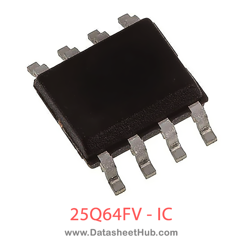
| Package | DIP, SOIC 8Pin Type |
| Manufacturer | Winbond |
| Datasheet | Download PDF  |
Datasheet
25Q64FV features
- Family of SpiFlash Memories
- – W25Q64FV: 64M-bit / 8M-byte (8,388,608)
- Standard SPI: CLK, /CS, DI, DO, /WP, /Hold
- Dual SPI: CLK, /CS, IO0, IO1, /WP, /Hold
- Quad SPI: CLK, /CS, IO0, IO1, IO2, IO3
- QPI: CLK, /CS, IO0, IO1, IO2, IO3
- Highest Performance Serial Flash
- 104MHz Standard/Dual/Quad SPI clocks
- 208/416MHz equivalent Dual/Quad SPI
- 50MB/S continuous data transfer rate
- More than 20-year data retention
- More than 100,000 erase/program cycles
- Efficient “Continuous Read” and QPI Mode
- Continuous Read with 8/16/32/64-Byte Wrap
- As few as 8 clocks to address memory
- Quad Peripheral Interface (QPI) reduces instruction overhead
- Allows true XIP (execute in place) operation
- Outperforms X16 Parallel Flash
- Low Power, Wide Temperature Range Single 2.7 to 3.6V supply 4mA active current, <1µA Power-down (typ.) -40°C to +85°C operating range
- Single 2.7 to 3.6V supply
- 4mA active current, <1µA Power-down (typ.)
- -40°C to +85°C operating range
- Flexible Architecture with 4KB sectors
- Uniform Sector Erase (4K-bytes)
- Uniform Block Erase (32K and 64K-bytes)
- Program 1 to 256 byte per programmable page
- Erase/Program Suspend & Resume
- Advanced Security Features
- Software and Hardware Write-Protect
- Top/Bottom, 4KB complement array protection
- Power Supply Lock-Down and OTP protection
- 64-Bit Unique ID for each device
- Discoverable Parameters (SFDP) Register
- 3X256-Bytes Security Registers with OTP locks
- Volatile & Non-volatile Status Register Bits
- Space Efficient Packaging
- 8-pin SOIC/VSOP 208-mil
- 8-pad WSON 6x5-mm/8x6-mm
- 8-pad XSON 4x4-mm
- 16-pin SOIC 300-mil
25Q64FV pinout

Absolute maximum ratings
| Parameter | Symbol | Value | Unit | Conditions |
|---|---|---|---|---|
| Supply Voltage | VCC | –0.6 to 4.6V | V | |
| Voltage Applied to Any Pin | VIO | –0.6 to VCC+0.4 | V | Relative to Ground |
| Transient Voltage on any Pin | VIOT | –2.0V to VCC+2.0V | V | <20nS Transient Relative to Ground |
| Storage Temperature | TSTG | –65 to +150 | °C | |
| Electrostatic Discharge Voltage | VESD(3) | –2000 to +2000 | V | Human Body Model |
25Q64FV applications
- Industrial Automation
- Networking Equipment
- Automotive Electronics
- IoT Devices
More about 25Q64FV
25Q64FV Features
- Family of SpiFlash Memories
- Highest Performance Serial Flash
- Efficient “Continuous Read” and QPI Mode
- Low Power, Wide Temperature Range
- Flexible Architecture with 4KB sectors
- Advanced Security Features
- Space Efficient Packaging
25Q64FV Absolute Maximum Ratings
| PARAMETERS | SYMBOL | CONDITIONS | RANGE | UNIT |
|---|---|---|---|---|
| Lead Temperature | TLEAD | See Note | °C |
Notes:
- This device has been designed and tested for the specified operation ranges. Proper operation outside of these levels is not guaranteed. Exposure to absolute maximum ratings may affect device reliability. Exposure beyond absolute maximum ratings may cause permanent damage.
- JEDEC Std JESD22-A114A (C1=100pF, R1=1500 ohms, R2=500 ohms).
- Compliant with JEDEC Standard J-STD-20C for small body Sn-Pb or Pb-free (Green) assembly and the European directive on restrictions on hazardous substances (RoHS) 2002/95/EU.
SOIC/VSOP 208-mil, WSON 6x5/8x6-mm, XSON 4x4-mm and PDIP 300-mil
| PIN NO. | PIN NAME | I/O | FUNCTION |
|---|---|---|---|
| 1 | /CS | I | Chip Select Input |
| 2 | DO (IO1) | I/O | Data Output (Data Input Output 1)*1 |
| 3 | /WP (IO2) | I/O | Write Protect Input ( Data Input Output 2)*2 |
| 4 | GND | Ground | |
| 5 | DI (IO0) | I/O | Data Input (Data Input Output 0)*1 |
| 6 | CLK | I | Serial Clock Input |
| 7 | /HOLD (IO3) | I/O | Hold Input (Data Input Output 3)*2 |
| 8 | VCC | Power Supply |
*1 IO0 and IO1 are used for Standard and Dual SPI instructions *2 IO0 – IO3 are used for Quad SPI instructions
SOIC 300-mil
| PIN NO. | PIN NAME | I/O | FUNCTION |
|---|---|---|---|
| 1 | /HOLD (IO3) | I/O | Hold Input (Data Input Output 3)*2 |
| 2 | VCC | Power Supply | |
| 3 | N/C | No Connect | |
| 4 | N/C | No Connect | |
| 5 | N/C | No Connect | |
| 6 | N/C | No Connect | |
| 7 | /CS | I | Chip Select Input |
| 8 | DO (IO1) | I/O | Data Output (Data Input Output 1)*1 |
| 9 | /WP (IO2) | I/O | Write Protect Input (Data Input Output 2)*2 |
| 10 | GND | Ground | |
| 11 | N/C | No Connect | |
| 12 | N/C | No Connect | |
| 13 | N/C | No Connect | |
| 14 | N/C | No Connect | |
| 15 | DI (IO0) | I/O | Data Input (Data Input Output 0)*1 |
| 16 | CLK | I | Serial Clock Input |
*1 IO0 and IO1 are used for Standard and Dual SPI instructions *2 IO0 – IO3 are used for Quad SPI instructions
TFBGA 8x6-mm
| BALL NO. | PIN NAME | I/O | FUNCTION |
|---|---|---|---|
| B2 | CLK | I | Serial Clock Input |
| B3 | GND | Ground | |
| B4 | VCC | Power Supply | |
| C2 | /CS | I | Chip Select Input |
| C4 | /WP (IO2) | I/O | Write Protect Input (Data Input Output 2)*2 |
| D2 | DO (IO1) | I/O | Data Output (Data Input Output 1)*1 |
| D3 | DI (IO0) | I/O | Data Input (Data Input Output 0)*1 |
| D4 | /HOLD (IO3) | I/O | Hold Input (Data Input Output 3)*2 |
| Multiple | NC | No Connect |
*1 IO0 and IO1 are used for Standard and Dual SPI instructions
*2 IO0 – IO3 are used for Quad SPI instructions
WLCSP
| BALL NO. | PIN NAME | I/O | FUNCTION |
|---|---|---|---|
| A2 | VCC | Power Supply | |
| B2 | /HOLD (IO3) | I/O | Hold Input (Data Input Output 3)*2 |
| C2 | CLK | I | Serial Clock Input |
| D2 | DI (IO0) | I/O | Data Input (Data Input Output 0)(1) |
| A3 | /CS | I | Chip Select Input |
| B3 | DO (IO1) | I/O | Data Output (Data Input Output 1)(1) |
| C3 | /WP (IO2) | I/O | Write Protect Input (Data Input Output 2)(2) |
| D3 | GND | Ground | |
| Multiple | NC | No Connect |
Notes:
- IO0 and IO1 are used for Standard and Dual SPI instructions
Comments 0
Leave a comment