
L512F Sensata-Crydom Thyristor Bridge Rectifier Module
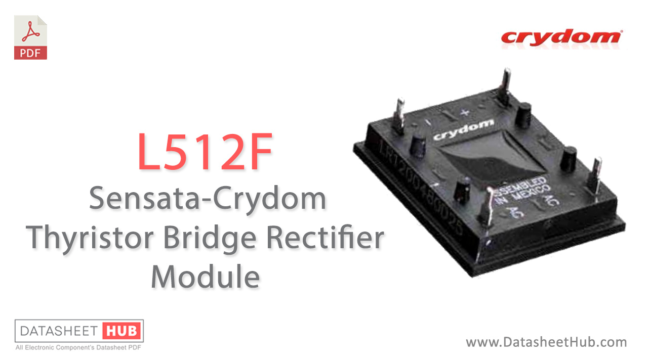
L512F overview
The L512F Sensata-Crydom Thyristor Bridge Rectifier Module represents a significant advancement in power electronics, designed to meet the demanding requirements of modern industrial applications. This robust and versatile module leverages thyristor technology to convert alternating current (AC) to direct current (DC) efficiently, ensuring reliable performance in a variety of high-power environments. Its innovative design and superior engineering make it an ideal solution for applications ranging from motor drives and power supplies to renewable energy systems. In this article, we will explore the key features, technical specifications, and practical applications of the L512F module
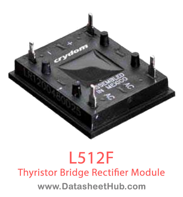
The L512F is a 6-pin PCB mount SCR/Diode Power Module that features a low profile. Designed for printed circuit board connections. Freewheeling diode included.
- 25A Load Current
- 240VAC Line Voltage
- 0.5W Average gate power
- 5V Maximum peak reverse gate voltage
- 2500Vrms Isolation voltage
Key specifications
Datasheet
L512F features
- Low Profile
- 7 Different Circuits to Choose from
- Designed for Printed Circuit Board Connections
- UL Recognized E72445
L512F specifications
| Maximum DC Output Current (Tc = 85°C) | L3 15 A / L5 25 A / L6 42.5 A |
|---|---|
| Maximum Voltage Drop @ Amps Peak | L3 2.2V @ 15A / L5 1.65V @ 25A / L6 1.6V @ 42.5A |
| Operating Junction Temperature Range | L5 -40 - 125°C |
| Critical Rate of Rise of On-State Current @ TJ=125°C | L5 100A/µs |
| Critical Rate of Rise of Off-State Voltage [V/µs] | L5 500A/µs120 (400VRRM) 240 (600VRRM) |
| AC Line Input Voltage (Repetitive Peak Reverse Voltage) | L5 280(800VRRM) 480(1200VRRM) |
| Maximum Non-Repetitive Surge Current (1/2 Cycle, 60 Hz) [A] | L3 225 / L5 300 / L6 600 |
| Maximum I²T for Fusing (t=8.3ms) [A²sec] | L3 210 / L5 375 / L6 1500 |
| Maximum Required Gate Current to Trigger @ 25°C [mA] | L3 60 / L5 60 / L6 80 |
| Maximum Required Gate Voltage to Trigger @ 25°C [V] | L3 2.5 / L5 2.5 / L6 3.0 |
| Average Gate Power [W] | L3 0.5 / L5 0.5 / L6 0.5 |
| Maximum Peak Reverse Gate Voltage [V] | L3 5.0 / L5 5.0 / L6 5.0 |
| Maximum Thermal Resistance, Junction to Ceramic Base per Chip [°C/W] | L3 1.25°C/W / L5 0.9°C/W / L6 0.7°C/W |
| Isolation Voltage [Vrms] | L5 2500 |
L512F applications
- Power Management
- Motor Drives
- HVAC Systems
- Industrial Automation etc
Application circuit

More about L512F
General Specificaions
| Description | Value |
|---|---|
| Weight (typical) | .5 oz (14.4g) |
Warnings
Risk of material damage and hot enclosure. Side panels may be hot, allow the product to cool before touching. Follow proper mounting instructions including torque values.
Download L512F Datasheet
Comments 0
Leave a comment