
Arduino Micro ATMega32U4 Development Board overview
The Arduino Micro is a microcontroller board based on the ATmega32u4. The dev board has 20 digital input/output pins (of which 7 can be used as PWM outputs and 12 as analog inputs), a 16 MHz crystal oscillator, a micro USB connection, an ICSP header, and a reset button, constituting everything needed to support the microcontroller; The Arduino Micro has a form factor that enables it to be easily placed on a breadboard. The form factor is similar to that of Arduino Leonardo in that the ATmega32u4 has built-in USB communication, eliminating the need for a secondary processor. This allows the Micro to appear to a connected computer as a mouse and keyboard, in addition to a virtual (CDC) serial / COM port. It
Arduino Micro is intended for semi-permanent installation in objects or exhibitions. The board comes
without pre-mounted headers, allowing the use of various types of connectors or direct soldering of
wires. The pin layout is compatible with Arduino shields. The 3.3V versions of the Micro can be powered
with a battery.
Key specifications
Datasheet
Arduino Micro ATMega32U4 Development Board features
- ATmegau32U4 running at 8MHz/16MHz with external resonator (0.5% tolerance)
- Low-voltage board needs no interfacing circuitry to popular 3.3V devices and modules (GPS, accelerometers, sensors, etc)
- 0.8mm Thin PCB
- USB connection off board
- Weighs less than 2 grams!
- Supports auto-reset
- 3.3V regulator
- Max 150mA output
- Over current protected
- DC input 3.3V up to 12V
Arduino Micro ATMega32U4 Development Board pinout
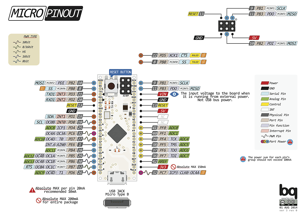
| Pin | Name | Description |
|---|---|---|
| 1 | MOSI | Master out slave in pin |
| 2 | SS | Slave Select pin |
| 3 | TX1 | Serial Port TXD 1 |
| 4 | RX1 | Serial Port RXD 1 |
| 5 | RST | Reset Pin |
| 6 | GND | Ground Pin |
| 7 | D2 | Digital Pin 2 |
| 8 | D3 | Digital Pin 3 |
| 9 | D4 | Digital Pin 4 |
| 10 | D5 | Digital Pin 5 |
| 11 | D6 | Digital Pin 6 |
| 12 | D7 | Digital Pin 7 |
| 13 | D8 | Digital Pin 8 |
| 14 | D9 | Digital Pin 9 |
| 15 | D10 | Digital Pin 10 |
| 16 | D11 | Digital Pin 11 |
| 17 | D12 | Digital Pin 12 |
| 18 | D13 | Digital Pin 13 |
| 19 | 3V3 | Chip Supply Voltage 3.3V |
| 20 | REF | Analog Reference Voltage |
| 21 | A0 | Analog I/O pin 1 |
| 22 | A1 | Analog I/O pin 2 |
| 23 | A2 | Analog I/O pin 3 |
| 24 | A3 | Analog I/O pin 4 |
Show all 34 pins
| Pin | Name | Description |
|---|---|---|
| 25 | A4 | Analog I/O pin 5 |
| 26 | A5 | Analog I/O pin 6 |
| 27 | NC | Not Connected |
| 28 | NC | Not Connected |
| 29 | 5V | Chip Supply Voltage 5V |
| 30 | RST | Reset Pin |
| 31 | GND | Ground Pin |
| 32 | VIN | 7-12V Output or Input |
| 33 | MISO | Master in slave out pin |
| 34 | SCK | Input Clock Pin |
Arduino Micro ATMega32U4 Development Board specifications
| Microcontroller | ATmega32u4 |
|---|---|
| Operating voltage | 5V |
| Input voltage (recommended) | 7-12V |
| Input voltage (limit) | 6-20 V |
| Digital Inputs/Outputs | 20 |
| PWM channels | 7 |
| Analog input channels | 12 |
| DC current through input/output | 40 mA |
| DC current for 3.3V output | 50mA |
| Flash | 32 KB (ATmega32u4) of which 4 KB used for the bootloader |
| RAM | 2.5 KB (ATmega32u4) |
| EEPROM | 1 KB (ATmega32u4) |
| Clock frequency | 16 MHz |
Arduino Micro ATMega32U4 Development Board applications
- Parking Lot Counter
- Embedded systems
- Home Automation
- Industrial Automation
Comments 0
Leave a comment