

ATmega32A Datasheet – 8-Bit AVR Microcontroller
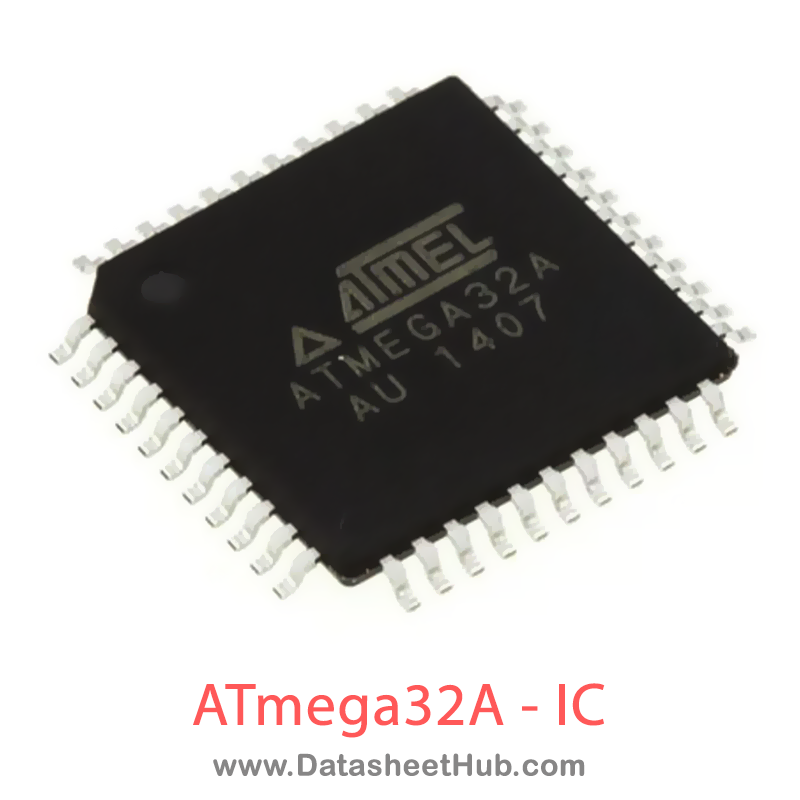
ATmega32A overview
The ATmega32A is an 8-Bit AVR Microcontroller made by Microchip Technology, supplied in these packages: 44-lead TQFP, 40pin DIP, 44-pad QFN Type. The absolute maximum ratings table on this page lists the 4 limits from the manufacturer's datasheet that must not be exceeded. This page brings together the ATmega32A pinout and maximum ratings, with the full datasheet PDF to preview below or download.
The ATmega32A is a low power, CMOS 8-bit microcontrollers based on the AVR® enhanced RISC architecture. The ATmega32A is a 40/44-pins device with 32 KB Flash, 2 KB SRAM and 1 KB EEPROM. By executing instructions in a single clock cycle, the devices achieve CPU throughput approaching one million instructions per second (MIPS) per megahertz, allowing the system designer to optimize power consumption versus processing speed.
Datasheet
ATmega32A features
- High-performance, Low-power AVR® 8-bit Microcontroller
- Advanced RISC Architecture
- 131 Powerful Instructions – Most Single-clock Cycle Execution
- 32 × 8 General Purpose Working Registers
- Fully Static Operation
- Up to 16MIPS Throughput at 16MHz
- On-chip 2-cycle Multiplier
- High Endurance Non-volatile Memory segments
- 32Kbytes of In-System Self-programmable Flash program memory1024Bytes EEPROM2Kbytes Internal SRAMWrite/Erase Cycles: 10,000 Flash/100,000 EEPROMData retention: 20 years at 85°C/100 years at 25°COptional Boot Code Section with Independent Lock BitsIn-System Programming by On-chip Boot Program True Read-While-Write Operation
- In-System Programming by On-chip Boot Program True Read-While-Write Operation
- Programming Lock for Software Security
- JTAG (IEEE std. 1149.1 Compliant) Interface
- Boundary-scan Capabilities According to the JTAG Standard
- Extensive On-chip Debug Support
- Programming of Flash, EEPROM, Fuses, and Lock Bits through the JTAG Interface
- QTouch® Library Support
- Capacitive touch buttons, sliders and wheels
- QTouch and QMatrix™ acquisition
- Up to 64 sense channels
- Peripheral Features
- Two 8-bit Timer/Counters with Separate Prescalers and Compare Modes
- One 16-bit Timer/Counter with Separate Prescaler, Compare Mode, and Capture Mode
- Real Time Counter with Separate Oscillator
- Four PWM Channels
- 8-channel, 10-bit ADC
- 8 Single-ended Channels
- 7 Differential Channels in TQFP Package Only
- 2 Differential Channels with Programmable Gain at 1x, 10x, or 200x
- Byte-oriented Two-wire Serial Interface
- Programmable Serial USART
- Master/Slave SPI Serial Interface
- Programmable Watchdog Timer with Separate On-chip Oscillator
- On-chip Analog Comparator
- Special Microcontroller Features
- Power-on Reset and Programmable Brown-out Detection
- Internal Calibrated RC Oscillator
- External and Internal Interrupt Sources
- Six Sleep Modes: Idle, ADC Noise Reduction, Power-save, Power-down, Standby and Extended Standby
- I/O and Packages32 Programmable I/O Lines 40-pin PDIP, 44-lead TQFP, and 44-pad QFN/MLF
- 32 Programmable I/O Lines
ATmega32A pinout
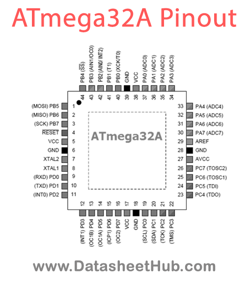
| Name | Description |
|---|---|
| VCC | Digital supply voltage |
| GND | Ground |
| Port A (PA7:PA0) | Port A serves as the analog inputs to the A/D Converter.Port A also serves as an 8-bit bi-directional I/O port, if the A/D Converter is not used. Port pins can provide internal pull-up resistors (selected for each bit). The Port A output buffers have symmetrical drive characteristics with both high |
| Port B (PB7:PB0) | Port B is an 8-bit bi-directional I/O port with internal pull-up resistors (selected for each bit). The Port B output buf- fers have symmetrical drive characteristics with both high sink and source capability. As inputs, Port B pins that are externally pulled low will source current if the pull-up r |
| Port C (PC7:PC0) | Port C is an 8-bit bi-directional I/O port with internal pull-up resistors (selected for each bit). The Port C output buf- fers have symmetrical drive characteristics with both high sink and source capability. As inputs, Port C pins that are externally pulled low will source current if the pull-up r |
| Port D (PD7:PD0) | Port D is an 8-bit bi-directional I/O port with internal pull-up resistors (selected for each bit). The Port D output buf- fers have symmetrical drive characteristics with both high sink and source capability. As inputs, Port D pins that are externally pulled low will source current if the pull-up r |
| RESET | Reset Input. A low level on this pin for longer than the minimum pulse length will generate a reset, even if the clock is not running. |
| XTAL 1 | Input to the inverting Oscillator amplifier and input to the internal clock operating circuit. |
| XTAL 2 | Output from the inverting Oscillator amplifier. |
| AVCC | AVCC is the supply voltage pin for Port A and the A/D Converter. It should be externally connected to VCC, even if the ADC is not used. If the ADC is used, it should be connected to VCC through a low-pass filter. |
| AREF | AREF is the analog reference pin for the A/D Converter. |
Absolute maximum ratings
| Parameter | Value |
|---|---|
| Operating Temperature | -55°C to +125°C |
| Storage Temperature | -65°C to +150°C |
| DC Current per I/O Pin | 40.0 mA |
| DC Current VCC and GND Pins | 200.0 mA and400.0 mA TQFP/MLF |
ATmega32A applications
- Embedded Systems
- Robotics
- IoT Devices
- Industrial Control
- Home Automation
Comments 0
Leave a comment