

CD4508-Dual 4-bit latch with three-state outputs
Package CDIP-24, SOIC-24, SO-24, TSSOP-24 Series CD4000 (CMOS) Status Active (9-Mar-2021)
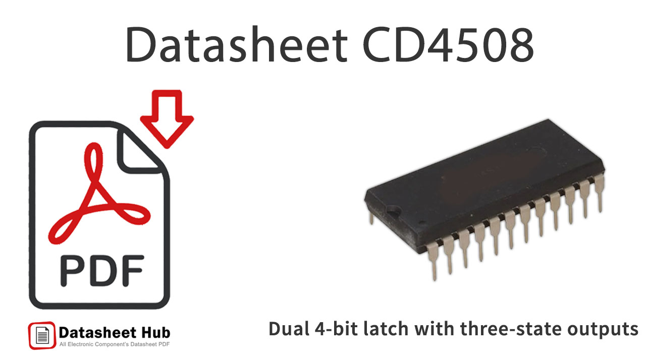
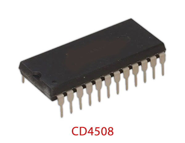
CD4508 overview
CD4508 belongs to the 4000 Series CMOS Logic Family of Integrated Circuits (IC's) constructed with N- and P-channel enhancement mode transistors. CD4508 has a Dual 4-bit latch with three-state outputs
CD4508 has a supply voltage range of 5V to 20V, which is much higher than any contemporary logic family. It has buffered output which improves transfer characteristics by providing very high gain. All inputs are protected against static discharge with diodes to VDD and VSS.
Datasheet
cd4508b.pdf
CD4508 features
- Two independent 4-bit latches
- Individual master reset for each 4-bit latch
- 3-state outputs with high-impedance state for bus line applications
- Medium-speed operation: tpHL = tPLH 70 ns(typ.) at VpD 10 V and CL= 50 pF
- (typ.) at VpD 10 V and CL= 50 pF
- Standard Symmetrical Output Characteristics
- 100% Tested for Maximum Quiescent Current at 20V
- 5V, 10V, and 15V Parametric Ratings
- Maximum Input Current of 1μA at 18V Over Full Package Temperature Range; 100nA at 18V and +25oC
- Noise Margin (Over Full Package Temperature Range):1V at VDD = 5V2V at VDD = 10V2.5V at VDD = 15V
- 1V at VDD = 5V
- 2V at VDD = 10V
- 2.5V at VDD = 15V
CD4508 pinout
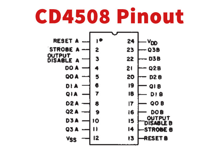
| Pin | Name | Description |
|---|---|---|
| 1 | RESET A | Reset Pin A |
| 2 | STROBE A | Strobe Pin A |
| 3 | DISABLE OUTPUT A | Disable Output Pin A |
| 4 | D0 A | Data Input Pin D0 A |
| 5 | Q0 A | Data Output Pin Q0 A |
| 6 | D1 A | Data Input Pin D1 A |
| 7 | Q1 A | Data Output Pin Q1 A |
| 8 | D2 A | Data Input Pin D2 A |
| 9 | Q2 A | Data Output Pin Q2 A |
| 10 | D3 A | Data Input Pin D3 A |
| 11 | Q3 A | Data Output Pin Q3 A |
| 12 | VSS | Supply Voltage |
| 13 | RESET B | Reset Pin B |
| 14 | STROBE B | Strobe Pin B |
| 15 | DISABLE OUTPUT B | Disable Output Pin B |
| 16 | D0 B | Data Input Pin D0 B |
| 17 | Q0 B | Data Output Pin Q0 B |
| 18 | D1 B | Data Input Pin D1 B |
| 19 | Q1 B | Data Output Pin Q1 B |
| 20 | D2 B | Data Input Pin D2 B |
| 21 | Q2 B | Data Output Pin Q2 B |
| 22 | D3 B | Data Input Pin D3 B |
| 23 | Q3 B | Data Output Pin Q3 B |
| 24 | VDD | Drain Voltage |
Absolute maximum ratings
| Parameter | Value |
|---|---|
| DC Supply Voltage Range, (VDD) | -0.5V to +20V (Voltage Referenced to VSS Terminals) |
| Input Voltage Range, All Inputs | -0.5V to VDD +0.5V |
| DC Input Current, Any One Input | ±10mA |
| Operating Temperature Range | -55oC to +125oC Package Types D, F, K, H |
| Storage Temperature Range (TSTG) | -65oC to +150oC |
| Lead Temperature (During Soldering) | +265oC |
CD4508 applications
- Buffer storage
- Holding registers
- Data storage and multiplexing
More about CD4508
Absolute Maximum Ratings
- Lead Temperature (During Soldering): +265oC
- At Distance 1/16 ± 1/32 Inch (1.59mm ± 0.79mm) from case for 10s Maximum
Comments 0
Leave a comment