

LMX2581 Datasheet – Wideband Frequency Synthesizer
Wideband Frequency Synthesizer with Integrated VCO

LMX2581 overview
The LMX2581 is a Wideband Frequency Synthesizer with Integrated VCO made by Texas Instruments, supplied in a WQFN 32 Pin ( 5.00 mm x 5.00 mm ) package. The absolute maximum ratings table on this page lists the 5 limits from the manufacturer's datasheet that must not be exceeded. This page brings together the LMX2581 pinout and maximum ratings, with the full datasheet PDF to preview below or download.
The LMX2581 is a low noise wideband frequency synthesizer that integrates a delta-sigma fractional N PLL, multiple core VCO, programmable output divider, and two differential output buffers. The VCO frequency range is from 1880 to 3760 MHz and can be sent directly to the output buffers or divided down by even values from 2 to 38. Each buffer is capable of output power from -3 to +12 dBm at 2700 MHz integrated low noise LDOs are used for superior noise immunity and consistent performance.
This synthesizer is a highly programmable device and it enables the user to optimize its performance. In fractional mode, the denominator and the modulator order are programmable and can be configured with dithering as well. The user also has the ability to directly specify a VCO core or entirely bypass the internal VCO. Finally, many convenient features are included such as power down, Fastlock, auto mute, and lock detection. All registers can be programmed through a simple 3 wire interface and a read back feature is also available.
The LMX2581 operates on a single 3.3 V supply and comes in a 32 pin 5.0 mm × 5.0 mm WQFN package
Datasheet
LMX2581 features
- Output Frequency from 50 to 3760 MHz
- Input Clock Frequency up to 900 MHz
- Phase Detector Frequency up to 200 MHz
- Supports Fractional and Integer Modes
- 229 dBc/Hz Normalized PLL Phase Noise
- 120.8 dBc/Hz Normalized PLL 1/f Noise .
- 137 dBc/Hz VCO Phase Noise @ 1 MHz offset for a 2.5 GHz Carrier
- 100 fs RMS Jitter in Integer Mode
- Programmable Fractional Modulator Order
- Programmable Fractional Denominator
- Programmable Output Power up to +12 dBm
- Programmable 32 Level Charge Pump Current
- Programmable Option to Use an External VCO
- Digital Lock Detect
- 3-Wire Serial Interface and Readback
- Single Supply Voltage from 3.15 V to 3.45 V
- Supports Logic Levels down to 1.6 V
LMX2581 pinout
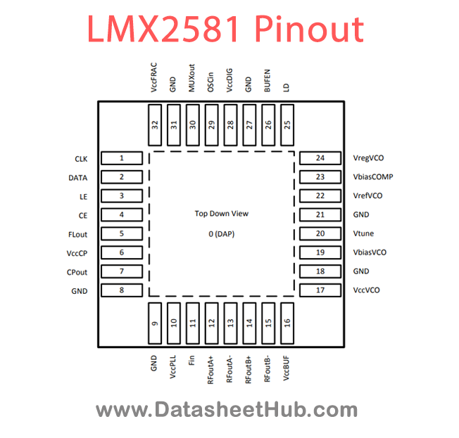
| Pin | Name | Description |
|---|---|---|
| 0 | DAP | The DAP should be grounded. |
| 1 | CLK | MICROWIRE Clock Input. High Impedance CMOS input. |
| 2 | DATA | MICROWIRE Data. High Impedance CMOS input. |
| 3 | LE | MICROWIRE Latch Enable. High Impedance CMOS input. |
| 4 | CE | Chip Enable Pin. |
| 5 | FLout | Fastlock Output. This can switch in an external resistor to the loop filter during locking to improve lock time. |
| 6 | VccCP | Charge Pump Supply. |
| 7 | CPout | Charge Pump Output. |
| 8 | GND | Ground for the Charge Pump. |
| 9 | GND | Ground for the N and R divider. |
| 10 | VccPLL | Supply for the PLL. |
| 11 | Fin | High frequency input pin for an external VCO. Leave Open or Ground if not used. |
| 12 | RFoutA+ | Differential divided output. For single-ended operation, terminate the complimentary side with a load equivalent to the load at this Pin. |
| 13 | RFoutA- | Differential divided output. For single-ended operation, terminate the complimentary side with a load equivalent to the load at this pin. |
| 14 | RFoutB+ | Differential divided output. For single-ended operation, terminate the complimentary side with a load equivalent to the load at this pin. |
| 15 | RFoutB- | Differential divided output. For single-ended operation, terminate the complimentary side with a load equivalent to the load at this pin. |
| 16 | VccBUF | Supply for the Output Buffer. |
| 17 | VccVCO | Supply for the VCO. |
| 18 | GND | Ground Pin for the VCO. This can be attached to the regular ground. Ensure a solid trace connects this pin to the bypass capacitors on pins 19, 23, and 24. |
Absolute maximum ratings
| Parameter | Value | Unit |
|---|---|---|
| Vcc | Power Supply Voltage | -0.3 3.6 |
| VIN | Input Voltage to Pins other than Vcc Pins | -0.3 (Vcc + 0.3) |
| TL | Lead Temperature (solder 4 sec.) | +260 |
| TJ | Junction Temperature | +150 |
| VOSCin | Voltage on OSCin (Pin29) | ≤1.8 with Vcc Applied ≤1 with |
LMX2581 applications
- Wireless Infrastructure (UMTS, LTE, WiMax, Multi-Standard Base Stations)
- Broadband Wireless
- Test and Measurement
- Clock Generation
Comments 0
Leave a comment