
OB2262AP Datasheet – Current Mode PWM Controller
Highly integrated current mode PWM control IC
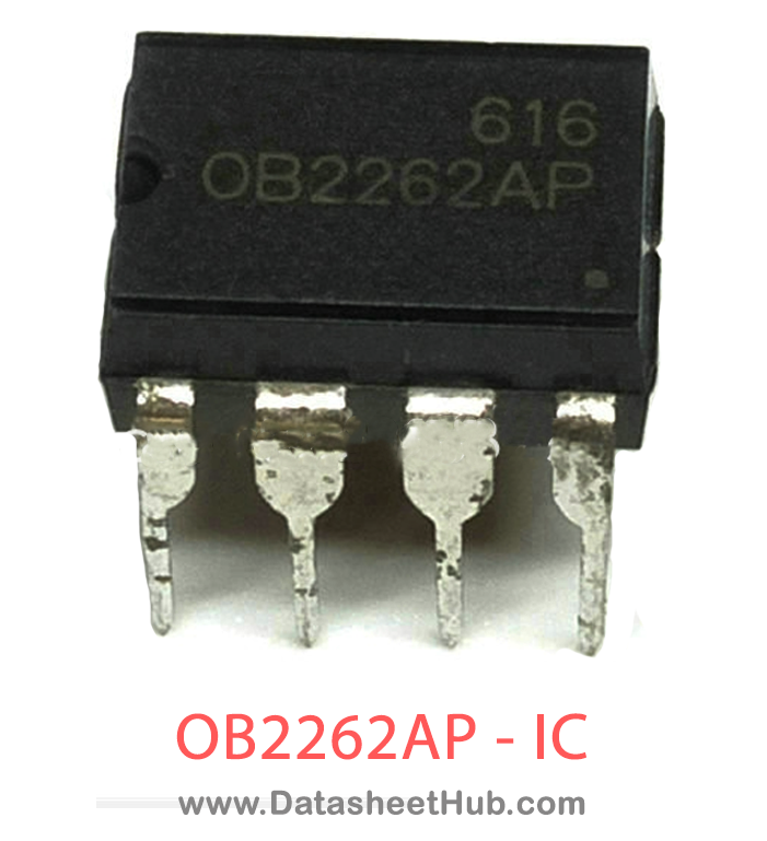
OB2262AP overview
The OB2262AP is a Highly integrated current mode PWM control IC, supplied in a DIP-8 Pin Type package. The absolute maximum ratings table on this page lists the 8 limits from the manufacturer's datasheet that must not be exceeded. This page brings together the OB2262AP pinout and maximum ratings, with the full datasheet PDF to preview below or download.
OB2262 is a highly integrated current mode PWM control IC optimized for high performance, low standby power and cost effective offline flyback converter applications in sub 30W range. PWM switching frequency at normal operation is externally programmable and trimmed to tight range. At no load or light load condition, the IC operates in extended ‘burst mode’ to minimize switching loss. Lower standby power and higher conversion efficiency is thus achieved.
VDD startup current and low operating current contribute to a reliable power on startup design with OB2262. A large value resistor could thus be used in the startup circuit to minimize the standby power.
The internal slope compensation improves system large signal stability and reduces the possible sub- harmonic oscillation at high PWM duty cycle output. Leading-edge blanking on current sense(CS) input removes the signal glitch due to snubber circuit diode reverse recovery and thus greatly reduces the external component count and system cost in the design. OB2262 offers complete protection coverage with automatic self-recovery feature including Cycle-by- Cycle current limiting (OCP), over load protection (OLP), VDD over voltage clamp and under voltage lockout (UVLO). The Gate-drive output is clamped to maximum 18V to protect the power MOSFET. Excellent EMI performance is achieved soft switching control at the totem pole gate drive output.
Datasheet
OB2262AP features
- Extended Burst Mode Control For Improved Efficiency and Minimum Standby Power Design
- Audio Noise Free Operation
- External Programmable PWM Switching Frequency
- Internal Synchronized Slope Compensation
- Low VDD Startup Current and Low Operating Current (1.4mA)
- Leading Edge Blanking on Current Sense Input
- Good Protection Coverage With Auto Self-Recovery
- VDD Over Voltage Clamp and Under Voltage Lockout with Hysteresis (UVLO)
- Gate Output Maximum Voltage Clamp (18V)
- On-Bright Proprietary Line Input Compensated Cycle-by-Cycle Over-current Threshold Setting For Constant Output Power Limiting Over Universal Input Voltage Range.
- Overload Protection (OLP).
OB2262AP pinout
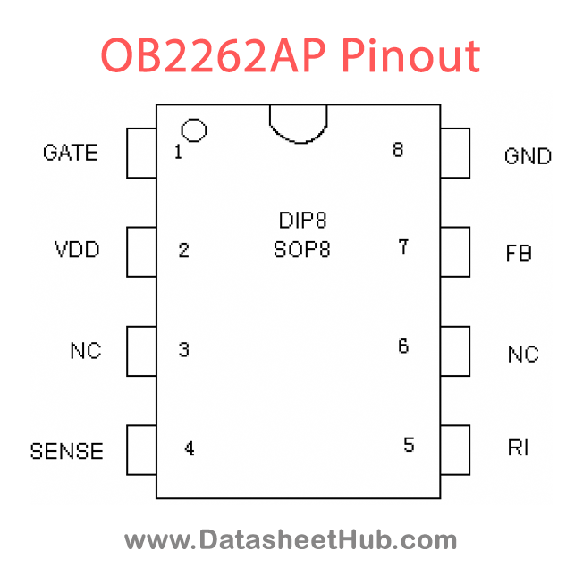
| Name | Description |
|---|---|
| GND | Ground |
| FB | Feedback input pin. The PWM duty cycle is determined by voltage level into this pin and the current-sense signal at Pin 6. |
| RI | Internal Oscillator frequency setting pin. A resistor connected between RI and GND sets the PWM frequency. |
| SENSE | Current sense input pin. Connected to MOSFET current sensing resistor node. |
| VDD | Chip DC power supply pin. |
| GATE | Totem-pole gate drive output for the power MOSFET. |
Absolute maximum ratings
| Parameter | Value |
|---|---|
| VDD DC Supply Voltage | 30 V |
| VDD Zener Clamp Voltage Note | VDD_Clamp+0.1V |
| VDD DC Clamp Current | 10 mA |
| VFB Input Voltage | -0.3 to 7V |
| VSENSE Input Voltage to Sense Pin | -0.3 to 7V |
| VRI Input Voltage to RI Pin | -0.3 to 7V |
| Min/Max Operating Junction Temperature TJ | -20 to 150 oC |
| Min/Max Storage Temperature Tstg | -55 to 160 oC |
OB2262AP applications
- Battery Charger
- Power Adaptor
- Set-Top Box Power Supplies
- Open-frame SMPS
Comments 0
Leave a comment