

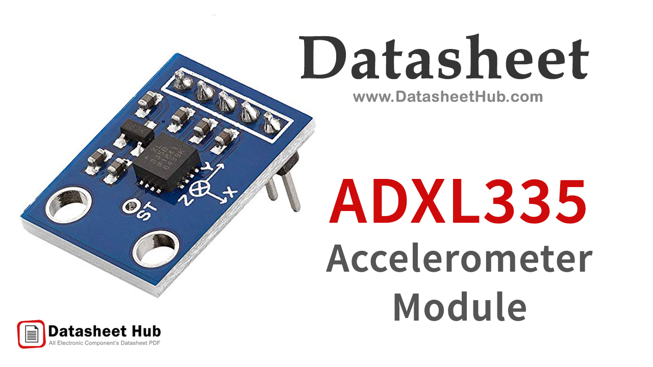
ADXL335 overview
The ADXL335 is a small, low-power, complete 3-axis accelerometer with signal-conditioned voltage outputs. It contains a polysilicon surface-micro machined sensor and signals conditioning circuitry. ADXL335 can measure the static acceleration of gravity in tilt-sensing applications, as well as dynamic acceleration resulting from motion, shock, or vibration. The basic structure of the ADXL335 accelerometer consists of fixed plates and moving plates. When the acceleration is applied on an axis capacitance between fixed plates and moving plates is changed. This results in a sensor output voltage amplitude that is proportional to the acceleration.
The user selects the bandwidth of the AXL335 accelerometer using the CX, CY, and CZ capacitors at the XOUT, YOUT, and ZOUT pins. Bandwidths can be selected to suit the application, with a range of 0.5 Hz to 1600 Hz for the X and Y axes, and a range of 0.5 Hz to 550 Hz for the Z axis. The module measures acceleration with a minimum full-scale range of ±3 g. The ADXL335 is available in a small, low profile, 4mm x 4mm x 1.4mm, 16 lead, plastic lead frame chip scale package.

Key specifications
Datasheet
ADXL335 features
- Operating Voltage: 3V to 6V DC
- Operating Current: 350μA
- Sensing Range: ±3g
- 3-axis sensing
- High Sensitivity for small movements
- Needs no external components
- Easy to use with Microcontrollers or even with normal Digital/Analog IC
- Small, cheap, and easily available
ADXL335 pinout
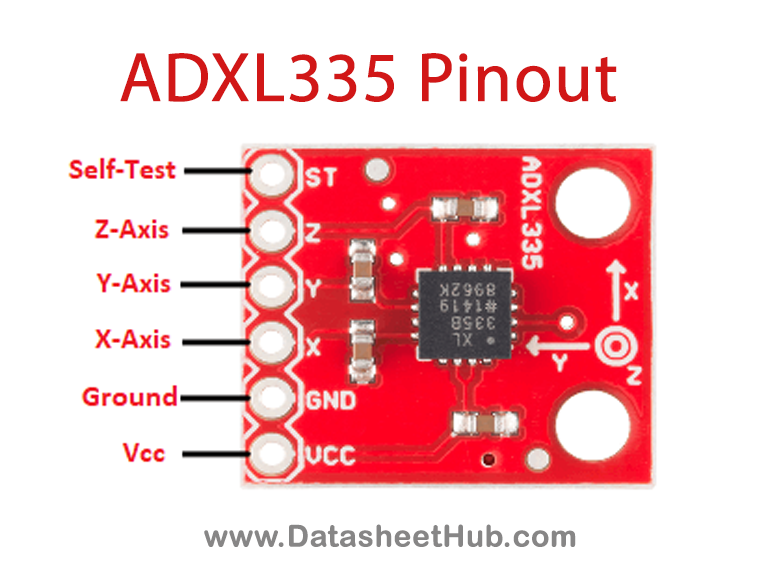
| Name | Description |
|---|---|
| Vcc | Chip Supply |
| GND | Ground |
| X | X-Axis Analog Output |
| Y | Y-Axis Analog Output |
| Z | Z-Axis Analog Output |
| ST | Self Test |
ADXL335 specifications
| Measurement Range | ±3.6g |
|---|---|
| Nonlinearity | ±0.3% |
| Cross-Axis Sensitivity | ±1% |
| Sensitivity at XOUT, YOUT, ZOUT | 300mV/g |
| Sensitivity Change Due to Temperature | ±0.01%/°C |
| Noise Density XOUT, YOUT | 150μg/√Hz RMS |
| RFILT Tolerance | 32 kΩ± 15% |
| Logic Input Low | +0.6V |
| Logic Input High | +2.4V |
ADXL335 applications
- Cost-sensitive, low power, motion- and tilt-sensing applications
- Mobile devices
- Gaming systems
- Disk drive protection
- Image stabilization
- Sports and health devices
- PDAs
- Pacemakers
More about ADXL335
ADXL335 Pinout
| Pin Name | Function | Description |
|---|---|---|
| Vcc | Chip Supply | The Vcc pin powers the module, typically with +5V |
| GND | Ground | Power Supply Ground |
| X | X-Axis Analog Output | X-axis Analog Output Pin |
| Y | Y-Axis Analog Output | Y-axis Analog Output Pin |
| Z | Z-Axis Analog Output | Z-axis Analog Output Pin |
| ST | Self Test | This pin controls the Self-Test feature |
ADXL335 Specifications
- Bandwidth with external capacitors = 1/(2 × π × 32 kΩ × C)
- bandwidth = 0.5 Hz.
- Self-test response changes cubically with VS
ADXL335 Datasheet
See Also: CD4059 Program Divide-by-N Counter | GY-NEO6MV2 Flight Control GPS Module | MPU6050 Gyrometer And Accelerometer Module
Comments 0
Leave a comment