

S29AL008D Datasheet – 8 Megabit, Boot Sector Flash Memory
8 Megabit / CMOS 3.0 Volt-only Boot Sector Flash Memory
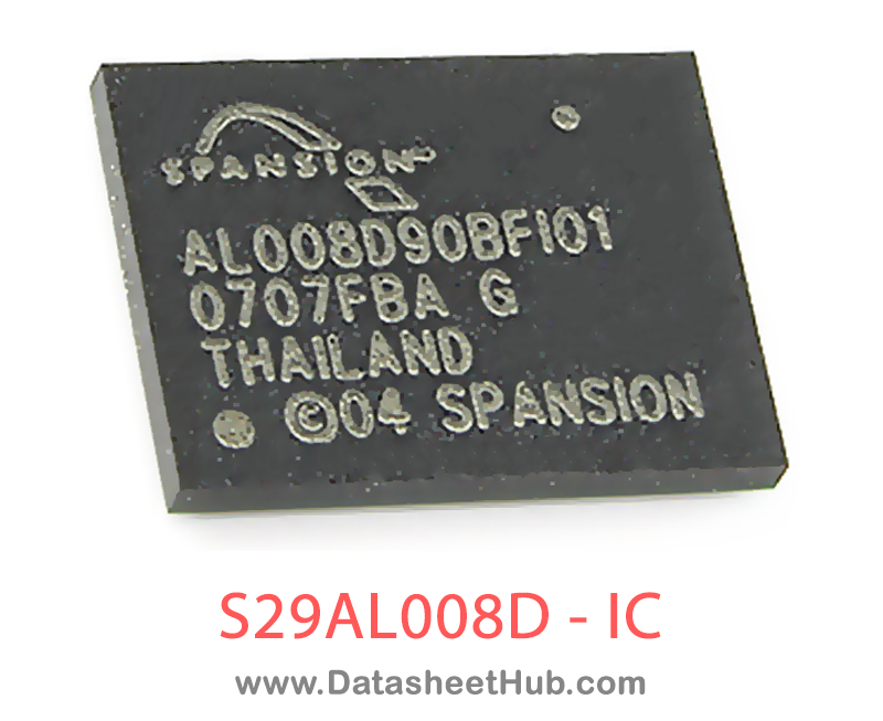
S29AL008D overview
The S29AL008D is an 8 Megabit / CMOS 3.0 Volt-only Boot Sector Flash Memory made by SPANSION, supplied in these packages: FBGA, TSOP 48 Pin , SO 44pin Type. The absolute maximum ratings table on this page lists the 6 limits from the manufacturer's datasheet that must not be exceeded. This page brings together the S29AL008D pinout and maximum ratings, with the full datasheet PDF to preview below or download.
The S29AL008D is an 8 Mbit, 3.0 volt-only Flash memory organized as 1,048,576 bytes or 524,288 words. The device is offered in 48-ball FBGA, 44-pin SO, and 48-pin TSOP packages. For more information, refer to publication number 21536. The word-wide data (x16) appears on DQ15–DQ0; the byte-wide (x8) data appears on DQ7–DQ0. This device requires only a single, 3.0 volt VCC supply to perform read, program, and erase operations. A standard EPROM programmer can also be used to program and erase the device.
This device is manufactured using Spansion’s 200 nm process technology, and offers all the features and benefits of the Am29LV800B, which was manufactured using 0.32 µm process technology.
The standard device offers access times of 55, 60, 70, and 90 ns, allowing high speed microprocessors to operate without wait states. To eliminate bus contention the device contains separate chip enable (CE#), write enable (WE#) and output enable (OE#) controls.
The device requires only a single 3.0 volt power supply for both read and write functions. Internally generated and regulated voltages are provided for the program and erase operations.
The device is entirely command set compatible with the JEDEC single-power-supply Flash standard. Commands are written to the command register using standard microprocessor write timings. Register contents serve as input to an internal state-machine that controls the erase and programming circuitry. Write cycles also internally latch addresses and data needed for the programming and erase operations. Reading data out of the device is similar to reading from other Flash or EPROM devices.
Device programming occurs by executing the program command sequence. This initiates the Embedded Program algorithm—an internal algorithm that automatically times the program pulse widths and verifies proper cell margin. The Unlock Bypass mode facilitates faster programming times by requiring only two write cycles to program data instead of four.
Device erasure occurs by executing the erase command sequence. This initiates the Embedded Erase algorithm—an internal algorithm that automatically preprograms the array (if it is not already programmed) before executing the erase operation. During erase, the device automatically times the erase pulse widths and verifies proper cell margin.
The host system can detect whether a program or erase operation is complete by observing the RY/BY# pin, or by reading the DQ7 (Data# Polling) and DQ6 (toggle) status bits. After a program or erase cycle is completed, the device is ready to read array data or accept another command.
The sector erase architecture allows memory sectors to be erased and reprogrammed without affecting the data contents of other sectors. The device is fully erased when shipped from the factory.
Hardware data protection measures include a low VCC detector that automatically inhibits write operations during power transitions. The hardware sector protection feature disables both program and erase operations in any combination of the sectors of memory. This can be achieved in-system or via programming equipment.
The Erase Suspend feature enables the user to put erase on hold for any period of time to read data from, or program data to, any sector that is not selected for erasure. True background erase can thus be achieved.
The hardware RESET# pin terminates any operation in progress and resets the internal state machine to reading array data. The RESET# pin may be tied to the system reset circuitry. A system reset would thus also reset the device, enabling the system microprocessor to read the boot-up firmware from the Flash memory.
The device offers two power-saving features. When addresses are stable for a specified amount of time, the device enters the automatic sleep mode. The system can also place the device into the standby mode. Power consumption is greatly reduced in both these modes. Spansion’s Flash technology combines years of Flash memory manufacturing experience to produce the highest levels of quality, reliability and cost effectiveness. The device electrically erases all bits within a sector simultaneously via Fowler-Nordheim tunneling. The data is programmed using hot electron injection
Datasheet
S29AL008D features
- Architectural Advantage
- Single Power Supply Operation 2.7 to 3.6 volt read and write operations for battery-powered applications
- 2.7 to 3.6 volt read and write operations for battery-powered applications
- Manufactured on 200 nm Process Technology Compatible with 0.32 µm and 230 nm Am29LV800 devices
- Compatible with 0.32 µm and 230 nm Am29LV800 devices
- Flexible Sector Architecture
- One 16-Kbyte, two 8-Kbyte, one 32-Kbyte, and fifteen 64-Kbyte sectors (byte mode)
- One 8 Kword, two 4 Kword, one 16-Kword, and fifteen 32-Kword sectors (word mode)
- Supports full chip erase
- Sector Protection features
- A hardware method of locking a sector to prevent any program or erase operations within that sector
- Sectors can be locked in-system or via programming equipment
- Temporary Sector Unprotect feature allows code changes in previously locked sectors
- Unlock Bypass Program Command Reduces overall programming time when issuing multiple program command sequences
- Reduces overall programming time when issuing multiple program command sequences
- Top or Bottom Boot Block Configurations Available
- Embedded Algorithms
- Embedded Erase algorithm automatically preprograms and erases the entire chip or any combination of designated sectors
- Embedded Program algorithm automatically writes and verifies data at specified addresses
- Compatibility with JEDEC Standards
- Pinout and software compatible with single-power supply Flash
- Superior inadvertent write protection
- Performance Characteristics
- High Performance Access times as fast as 55 ns Extended temperature range (-40°C to +125°C)
- Access times as fast as 55 ns
- Extended temperature range (-40°C to +125°C)
- Ultra-low Power Consumption (typical values at 5 MHz)
- 200 nA Automatic Sleep mode current
- 200 nA standby mode current
- 7 mA read current
- 15 mA program/erase current
- Cycling Endurance: 1,000,000 cycles per sector typical
- Data Retention: 20 years typical Reliable operation for the life of the system
- Reliable operation for the life of the system
- Package Option 48-ball FBGA 48-pin TSOP 44-pin SO
- 48-ball FBGA
- 48-pin TSOP
- 44-pin SO
- Software Features Data# Polling and Toggle Bits Provides a software method of detecting program or erase operation completion Erase Suspend/Erase Resume Suspends an erase operation to read data from, or program data to, a sector that is not being erased, then resumes the erase operation
- Data# Polling and Toggle Bits Provides a software method of detecting program or erase operation completion
S29AL008D pinout

| Name | Description |
|---|---|
| A0–A18 | 19 addresses |
| DQ0–DQ14 | 15 data inputs/outputs |
| DQ15/A-1 | DQ15 (data input/output, word mode), A-1 (LSB address input, byte mode) |
| BYTE# | Selects 8-bit or 16-bit mode |
| CE# | Chip enable |
| OE# | Output enable |
| WE# | Write enable |
| RESET# | Hardware reset pin, active low |
| RY/BY# | Ready/Busy# output |
| VCC | 3.0 volt-only single power supply (see Product Selector Guide on page 4 for speed options and voltage supply tolerances) |
| VSS | Device ground |
| NC | Pin not connected internally |
Absolute maximum ratings
| Parameter | Value |
|---|---|
| Storage Temperature Plastic Packages | –65°C to +150°C |
| Ambient Temperature with Power Applied | –65°C to +125°C |
| Voltage with Respect to Ground VCC (Note 1) | –0.5 V to +4.0 V |
| A9, OE#, and RESET# (Note 2) | –0.5 V to +12.5 V |
| All other pins (Note 1) | –0.5 V to VCC+0.5 V |
| Output Short Circuit Current (Note 3) | 200 mA |
S29AL008D applications
- Consumer Electronics
- Industrial Automation
- Networking Equipment
- IoT Devices
- Wearable Devices
Comments 0
Leave a comment