

SN608098 Datasheet – Power Supply Controller IC
Power Supply Controller ( Power IC Chip )

SN608098 overview
The SN608098 is a Power Supply Controller ( Power IC Chip ) made by Texas Instruments, supplied in a QFN 32pin package. The absolute maximum ratings table on this page lists the 13 limits from the manufacturer's datasheet that must not be exceeded. This page brings together the SN608098 pinout and maximum ratings, with the full datasheet PDF to preview below or download.
The RT8206A/B dual step-down, Switch Mode Power Supply (SMPS) controller generates logic supply voltages in battery powered systems. The RT8206A/B includes two Pulse Width Modulation (PWM) controllers fixed at 5V/3.3V or adjustable from 2V to 5.5V. An optional external charge pump can be monitored through SECFB (RT8206A). This device also features a linear regulator providing a fixed 5V output. The linear regulator provides up to 70mA output current with automatic linear regulator bootstrapping to the BYP input. The RT8206A/B includes on-board power up sequencing, the power good outputs, internal soft-start, and internal soft-discharge output that prevents negative voltages on shutdown.
A constant on-time PWM control scheme operates without sense resistors and provides 100ns response to load transients while maintaining a relatively constant switching frequency. The unique ultrasonic mode maintains the switching frequency above 25kHz, which eliminates noise in audio applications. Other features include Diode Emulation Mode (DEM), which maximizes efficiency in light load applications, and fixed frequency PWM mode, which reduces RF interference in sensitive application. The RT8206A/B is available in the WQFN-32L 5x5 package.
Datasheet
SN608098 features
- l Wide Input Voltage Range 6V to 25V
- Dual Fixed 5V/3.3V Outputs or Adjustable from 2V to 5.5V, 1.5% Accuracy
- l Secondary Feedback Input Maintains Charge Pump Voltage (RT8206A)
- Independent Enable and Power Good
- l 5V Fixed LDO Output : 70mA
- 2V Reference Voltage ±1% : 50mA
- l Constant ON-Time Control with 100ns Load Step Response
- Frequency Selectable via TON Setting
- l RDS(ON) Current Sensing and Programmable Current Limit
- Selectable PWM, DEM or Ultrasonic Mode
- l Internal Soft-Start with 5 Steps Current Limiting and Soft-Discharge
- High Efficiency Up to 97%
- l 5mW Quiescent Power Dissipation
- Thermal Shutdown
- RoHS Compliant and Halogen Free
SN608098 pinout
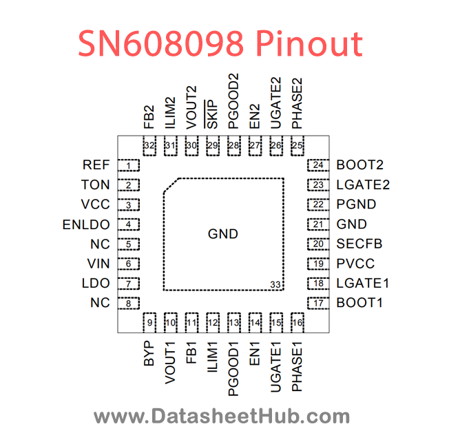
| Pin | Name | Description |
|---|---|---|
| 1 | REF | 2V Reference Output. Bypass to GND with a 0.22mF capacitor. REF can source up to 50mA for external loads. Loading REF degrades FBx and output accuracy according to the REF load regulation error. |
| 2 | TON | Frequency Select Input. (VOUT1/VOUT2 switching frequency, respectively) :TON = VCC, (200kHz / 250kHz) TON = REF, (300kHz / 375kHz) TON = GND, (400kHz / 500kHz) |
| 3 | VCC | Analog Supply Voltage Input for the PWM Core. Bypass to GND with a 1mF ceramic capacitor |
| 4 | ENLDO | LDO Enable Input. The REF/LDO is enabled if ENLDO is within logic high level and disable if ENLDO is less than the logic low level. |
| 5 | FB1 | SMPS1 Feedback Input. Connect FB1 to VCC or GND for fixed 5V operation. Connect FB1 to a resistive voltage divider from VOUT1 to GND to adjust output from 2V to 5.5V. |
| 6 | NC | NOT CONNECTED |
| 7 | VIN | Power supply Input. VIN is used for the constant on-time PWM one shot circuits. VIN is also used to power the linear regulators. The linear regulators are powered by SMPS1 if VOUT1 is set greater than 4.66V and BYP is tied to VOUT1. Connect VIN to the battery input and bypass with a 1mF capacitor. |
| 8 | LDO | Linear Regulator Output. LDO can provide a total of 70mA external loads. The LDO regulates a fixed 5V output. When the BYP is within 5V switchover threshold, the internal regulator shuts down and the LDO output pin connects to BYP through a 1.5L switch. Bypass LDO output with a minimum of 4.7mF cera |
| 9 | BYP | BYP is the switchover source voltage input for the LDO. |
| 10 | VOUT1 | SMPS1 Output Voltage Sense Input. Connect this pin to the SMPS1 output. VOUT1 is an input to the Constant on-time-PWM one-shot circuit. It also serves as the SMPS1 feedback input in fixed voltage mode. |
| 11 | ILIM1 | SMPS1 Current Limit Adjustment. The GND - PHASE1 current limit threshold is 1/10th the voltage seen at ILIM1 over a 0.5V to 2V range. There is an internal 5mA current source from VCC to ILIM1. The logic current limit threshold is default to 100mV if ILIM1 is higher than (VCC - 1V). |
| 12 | PGOOD1 | SMPS1 Power Good Open-Drain Output. PGOOD1 is low when the SMPS1 output voltage is more than 7.5% below the normal regulation point or during soft-start. PGOOD1 is high impedance when the output is in regulation and the soft-start circuit has terminated. PGOOD1 is low in shutdown. |
| 13 | EN1 | SMPS1 Enable Input. The SMPS1 will be enabled if EN1 is greater than the logic high level and disabled if EN1 is less than the logic low level. If EN1 is connected to REF, the SMPS1 starts after the SMPS2 reaches regulation (delay start). Drive EN1 below 0.8V to clear fault level and reset the fault |
| 14 | UGATE1 | High Side MOSFET Floating Gate Driver Output for SMPS1. UGATE1 swings between PHASE1 and BOOT1. |
| 15 | PHASE1 | Inductor Connection for SMPS1. PHASE1 is the internal lower supply rail for the UGATE1 high side gate driver. PHASE1 is the current sense input for the SMPS1. |
| 16 | BOOT1 | Boost Flying Capacitor Connection for SMPS1. Connect to an external capacitor according to the typical application circuits. |
| 17 | LGATE1 | SMPS1 Synchronous-Rectifier Gate drive Output. LGATE1 swings between PGND and PVCC. |
| 18 | PVCC | PVCC is the supply voltage for the low side MOSFET driver LGATEx. Connect a 5V power source to the PVCC pin (bypass with 1mF MLCC capacitor to PGND if necessary). There is an internal 10L connecting from PVCC to VCC. Make sure that both VCC and PVCC are bypassed with 1mF MLCC capacitors. |
| 19 | SECFB | The SECFB is used to monitor the optional external 14V charge pump. Connect a resistive voltage divider from the 14V charge pump output to GND to detect the output. If SECFB drops below the threshold voltage, LGATE1 will be turned on for 300ns. This will refresh the external charge pump driven by LG |
| 20 | NC | No Internal Connection. |
| 21,33 | GND | Analog Ground for both SMPS and LDO. The exposed pad must be soldered to a large PCB and connected to GND for maximum power dissipation. |
| 22 | PGND | Power Ground for SMPS controller. Connect PGND externally to the underside of the exposed pad. |
| 23 | LGATE2 | SMPS2 Synchronous-Rectifier Gate drive Output. LGATE2 swings between PGND and PVCC. |
| 24 | BOOT2 | Boost Flying Capacitor Connection for SMPS2. Connect this pin to an external capacitor according to the typical application circuits. |
Show all 32 pins
| Pin | Name | Description |
|---|---|---|
| 25 | PHASE2 | Inductor Connection for SMPS2. PHASE2 is the internal lower supply rail for the UGATE2 high side gate driver. PHASE2 is the current sense input for the SMPS2. |
| 26 | UGATE2 | High Side MOSFET Floating Gate Driver Output for SMPS2. UGATE2 swings between PHASE2 and BOOT2. |
| 27 | EN2 | SMPS2 Enable Input. The SMPS2 will be enabled if EN2 is greater than the logic high level and be disabled if EN2 is less than the logic low level. If EN2 is connected to REF, the SMPS2 starts after the SMPS1 reaches regulation (delay start). Drive EN2 below 0.8V to clear fault level and reset the fa |
| 28 | PGOOD2 | SMPS2 Power Good Open-Drain Output. PGOOD2 is low when the SMPS2 output voltage is more than 7.5% below the normal regulation point or during soft-start. PGOOD2 is high impedance when the output is in regulation and the soft-start circuit has terminated. PGOOD2 is low in shutdown. |
| 29 | SKIP | SMPS Operation Mode Control. SKIP = GND : DEM operationSKIP = REF : Ultrasonic Mode operation SKIP = VCC : PWM operation. |
| 30 | VOUT2 | SMPS2 Output Voltage Sense Input. Connect this pin to the SMPS2 output. VOUT2 is an input to the constant on-time-PWM one-shot circuit. It also serves as the SMPS2 feedback input in fixed voltage mode. |
| 31 | ILIM2 | SMPS2 Current Limit Adjustment. The GND - PHASE2 current limit threshold is 1/10th the voltage seen at ILIM2 over a 0.5V to 2V range. There is an internal 5mA current source from VCC to ILIM2. The logic current limit threshold is default to 100mV value if ILIM2 is higher than (VCC - 1V). |
| 32 | FB2 | SMPS2 Feedback Input. Connect FB2 to VCC or GND for fixed 3.3V operation. Connect FB2 to a resistive voltage divider from VOUT2 to GND to adjust output from 2V to 5.5V. |
Absolute maximum ratings
| Parameter | Value |
|---|---|
| VIN, ENLDO to GND | –0.3V to 30V |
| PHASEx to GNDDC<20ns | –0.3V to 30V–8V to 6V |
| BOOTx to PHASEx | –0.3V to 6V |
| VCC, ENx, SKIP, TON, PVCC, PGOODx, to GND | –0.3V to 6V |
| LDO, FBx, VOUTx, SECFB, REF, ILIMx to GND | –0.3V to (VCC + 0.3V) |
| UGATEx to PHASExDC<20ns | 0.3V to (PVCC + 0.3V)–5V to 7.5V |
| LGATEx, BYP to GNDDC<20ns | 0.3V to (PVCC + 0.3V) V to 7.5V |
| Power Dissipation, PD @ TA = 25°CWQFN-32L 5x5 | 2.778W |
| Package Thermal Resistance (Note 2) WQFN-32L 5x5, qJAWQFN-32L 5x5, qJC | 36°C/W7°C/W |
| Junction Temperature | 150°C |
| Lead Temperature (Soldering, 10 sec.) | 260°C |
| Storage Temperature Range | –65°C to 150°C |
| ESD SusceptibilityHBM (Human Body Mode) | 2kV200V |
SN608098 applications
- Notebook and Sub-Notebook Computers
- 3-Cell and 4-Cell Li+ Battery-Powered Devices
- Network Switches
- Industrial Networking
- Telephony Systems
- Internet Infrastructure
Comments 0
Leave a comment