

SN74LS47 Datasheet – BCD to 7-Segment Decoder / Driver
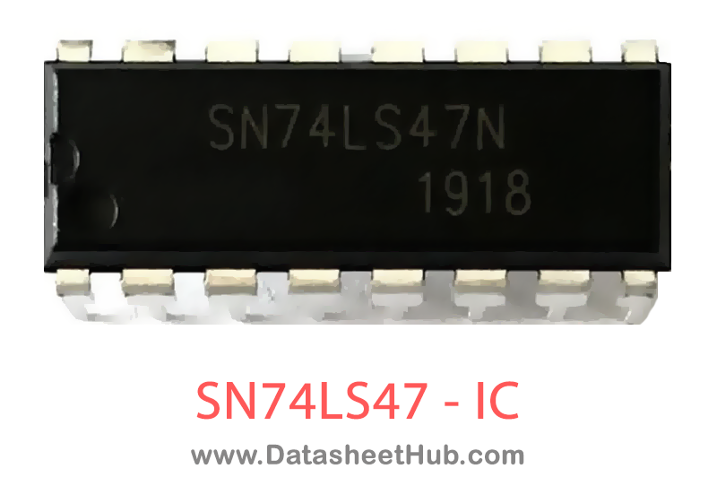
SN74LS47 overview
The SN74LS47 is a BCD to 7-Segment Decoder / Driver made by ON Semiconductor, supplied in these packages: DIP, SOIC 16 Pin Type. The absolute maximum ratings table on this page lists the 6 limits from the manufacturer's datasheet that must not be exceeded. This page brings together the SN74LS47 pinout and maximum ratings, with the full datasheet PDF to preview below or download.
The SN74LS47 are Low Power Schottky BCD to 7-Segment Decoder/ Drivers consisting of NAND gates, input buffers and seven AND-OR-INVERT gates. They offer active LOW, high sink current outputs for driving indicators directly. Seven NAND gates and one driver are connected in pairs to make BCD data and its complement available to the seven decoding AND-OR-INVERT gates. The remaining NAND gate and three input buffers provide lamp test, blanking input/ ripple-blanking output and ripple-blanking input.
The circuits accept 4-bit binary-coded-decimal (BCD) and, depending on the state of the auxiliary inputs, decodes this data to drive a 7-segment display indicator. The relative positive-logic output levels, as well as conditions required at the auxiliary inputs, are shown in the truth tables. Output configurations of the SN74LS47 are designed to withstand the relatively high voltages required for 7-segment indicators.
These outputs will withstand 15 V with a maximum reverse current of 250 mA. Indicator segments requiring up to 24 mA of current may be driven directly from the SN74LS47 high performance output transistors. Display patterns for BCD input counts above nine are unique symbols to authenticate input conditions.
The SN74LS47 incorporates automatic leading and/ or trailing-edge zero-blanking control (RBI and RBO). Lamp test (LT) may be performed at any time which the BI/ RBO node is a HIGH level. This device also contains an overriding blanking input (BI) which can be used to control the lamp intensity by varying the frequency and duty cycle of the BI input signal or to inhibit the outputs.
Datasheet
SN74LS47 features
- Intensity Modulation Capability (BI/RBO)
- Open Collector Outputs
- Lamp Test Provision Lamp
- Leading/ Trailing Zero Suppression
- Input Clamp Diodes Limit High-Speed Termination Effects
SN74LS47 pinout

| Name | Description |
|---|---|
| A, B, C, D | BCD Inputs Ripple |
| RBI | Blanking Input Lamp |
| LT | Test Input Blanking |
| BI/RBO | Input or Ripple |
| -- | Blanking Output |
| A, tog | Outputs |
Absolute maximum ratings
| Parameter | Symbol | Value | Unit |
|---|---|---|---|
| Supply Voltage | VCC | Min 4.75 / Type 5.0 / Max 5.25 | V |
| Operating Ambient Temperature Range | TA | Min 0 / Type 25 / Max 70 | °C |
| Output Current – High BI/RBO | IOH | Max –50 | A |
| Output Current – Low BI/RBO BI/RBO | IOL | Max 3.2 | mA |
| Off–State Output Voltage a to g | VO(off) | Max 15 | V |
| On–State Output Current a to g | IO(on) | Max 24 | mA |
SN74LS47 applications
- BCD to 7-Segment Display Decoder
- Digital Counters and Timers
- Numeric Display Systems
- Seven-Segment LED Displays
Comments 0
Leave a comment