

ACS712 Datasheet – Linear Current Sensor
Fully Integrated / Hall Effect-Based Linear Current Sensor
ACS712 overview
The Allegro™ ACS712 provides economical and precise solutions forAC or DC current sensing in industrial, commercial, and communications systems. The device package allows for easy implementation by the customer. Typical applications include motor control, load detection and management, switch- mode power supplies, and overcurrent fault protection. The device is not intended for automotive applications.
The device consists of a precise, low-offset, linear Hall circuit with a copper conduction path located near the surface of the die. Applied current flowing through this copper conduction path generates a magnetic field which the Hall IC converts into a proportional voltage. Device accuracy is optimized through the close proximity of the magnetic signal to the Hall transducer. A precise, proportional voltage is provided by the low-offset, chopper-stabilized BiCMOS Hall IC, which is programmed for accuracy after packaging.
The output of the device has a positive slope (>VIOUT(Q)) when an increasing current flows through the primary copper conduction path (from pins 1 and 2, to pins 3 and 4), which is the path used for current sampling. The internal resistance of this conductive path is 1.2 mΩ typical, providing low power loss. The thickness of the copper conductor allows survival of the device at up to 5× overcurrent conditions. The terminals of the conductive path are electrically isolated from the signal leads (pins 5 through 8). This allows the ACS712 to be used in applications requiring electrical isolation without the use of opto-isolators or other costly isolation techniques. The ACS712 is provided in a small, surface mount SOIC8 package. The lead frame is plated with 100% matte tin, which is compatible with standard lead (Pb) free printed circuit board assembly processes. Internally, the device is Pb-free, except for flip-chip high-temperature Pb-based solder balls, currently exempt from RoHS. The device is fully calibrated prior to shipment from the factory
| Part Number | ACS712 |
| Function | Fully Integrated / Hall Effect-Based Linear Current Sensor |
| Package | SOIC 8 Pin Type |
| Manufacturer | Allegro Micro Systems |
| Datasheet | Download PDF  |

Datasheet
ACS712 features
- Low-noise analog signal path
- Device bandwidth is set via the new FILTER pin
- 5 µs output rise time in response to step input current
- 80 kHz bandwidth
- Total output error 1.5% at TA= 25°C
- Small footprint, low-profile SOIC-8 package
- 1.2 mΩ internal conductor resistance
- 2.1 kVRMS minimum isolation voltage from pins 1-4 to pins 5-8
- 5.0 V, single supply operation
- 66 to 185 mV/A output sensitivity
- Output voltage proportional to AC or DC currents
- Factory-trimmed for accuracy
- Extremely stable output offset voltage
- Nearly zero magnetic hysteresis
- Ratiometric output from supply voltage
ACS712 pinout
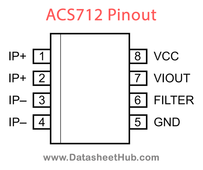
| Name | Description |
|---|---|
| IP+ | Terminals for current being sampled; fused internally |
| IP– | Terminals for current being sampled; fused internally |
| GND | Signal ground terminal |
| FILTER | Terminal for external capacitor that sets bandwidth |
| VIOUT | Analog output signal |
| VCC | Device power supply terminal |
Absolute maximum ratings
| Parameter | Symbol | Value | Unit |
|---|---|---|---|
| Supply Voltage | VCC | Rating 8 | V |
| Reverse Supply Voltage | VRCC | Rating –0.1 | V |
| Output Voltage | VIOUT | Rating 8 | V |
| Reverse Output Voltage | VRIOUT | Rating –0.1 | V |
| Output Current Source | IIOUT(Source) | Rating 3 | mA |
| Output Current Sink | IIOUT(Sink) | Rating 10 | mA |
| Overcurrent Transient Tolerance | IP | Notes 1 pulse, 100 ms / Rating 100 | A |
| Nominal Operating Ambient Temperature | TA | Notes Range E / Rating –40 to 85 | °C |
| Maximum Junction Temperature | TJ(max) | Rating 165 | °C |
| Storage Temperature | Tstg | Rating –65 to 170 | °C |
ACS712 applications
- Current Sensing
- Power Monitoring
- Battery Management
- Motor Control
- Overcurrent Protection
More about ACS712
Pin Definitions
| Number | Name | Description |
|---|---|---|
| 1 and 2 | IP+ | Terminals for current being sampled; fused internally |
| 3 and 4 | IP– | Terminals for current being sampled; fused internally |
Comments 0
Leave a comment