

CD4053 Triple 2-channel Multiplexer/Demultiplexer
Package SOIC, SOP, PDIP Series CD4000 (CMOS)
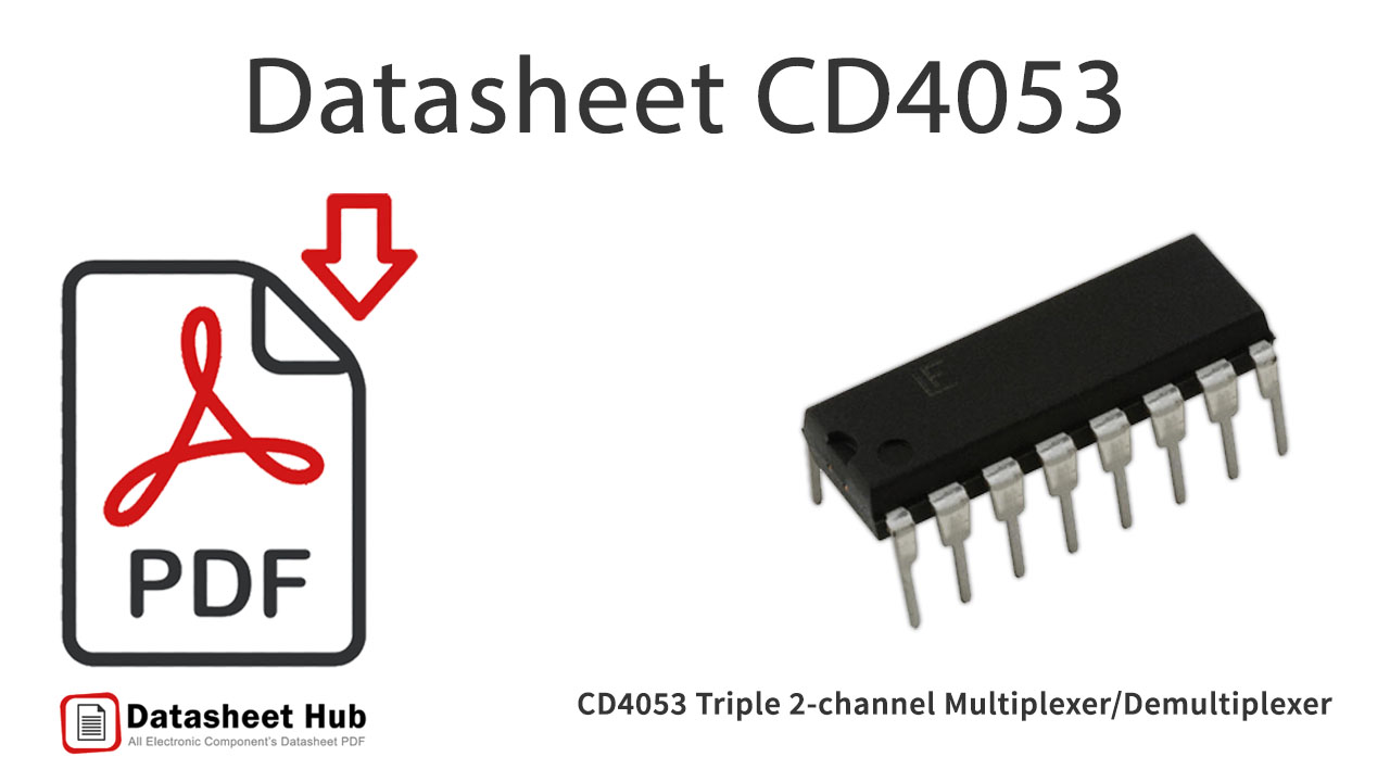
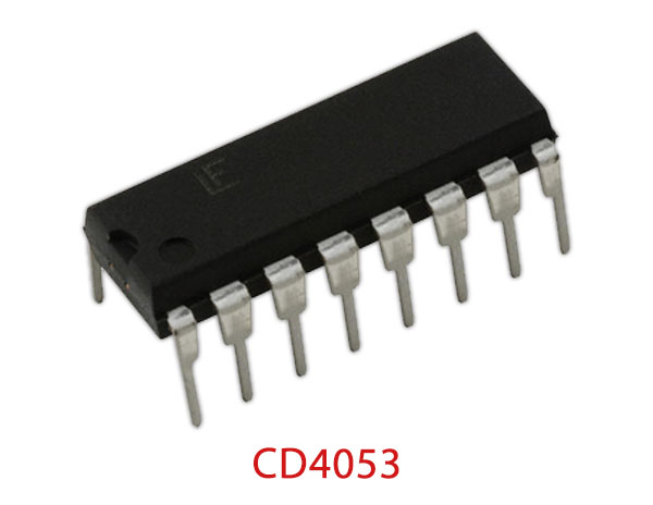
CD4053 overview
CD4053 belongs to the 4000 Series CMOS Logic Family of Integrated Circuits (IC's) constructed with N- and P-channel enhancement mode transistors. CD4053 has a Triple 2-channel Multiplexer/Demultiplexer
CD4053 has a supply voltage range of 5V to 20V, which is much higher than any contemporary logic family. It has buffered output which improves transfer characteristics by providing very high gain. All inputs are protected against static discharge with diodes to VDD and VSS.
Datasheet
cd4053.pdf
CD4053 features
- Wide range of digital and analog signal levels:digital 3 – 15V, analog to 15Vp-p
- digital 3 – 15V, analog to 15Vp-p
- Low “ON” resistance: 80Ω (typ.) over entire 15Vp-psignal-input range for VDD − VEE = 15V
- signal-input range for VDD − VEE = 15V
- High “OFF” resistance:channel leakage of ±10 pA (typ.) at VDD − VEE = 10V
- channel leakage of ±10 pA (typ.) at VDD − VEE = 10V
- Logic level conversion for digital addressing signals of3 – 15V (VDD − VSS = 3 – 15V) to switch analog signals to 15 Vp-p (VDD − VEE = 15V)
- 3 – 15V (VDD − VSS = 3 – 15V) to switch analog signals to 15 Vp-p (VDD − VEE = 15V)
- Matched switch characteristics: ∆RON = 5Ω (typ.) for VDD − VEE = 15V
- Very low quiescent power dissipation under alldigital-control input and supply conditions: 1 µ W (typ.) at VDD − VSS = VDD − VEE = 10V
- digital-control input and supply conditions: 1 µ W (typ.) at VDD − VSS = VDD − VEE = 10V
- Binary address decoding on chip
CD4053 pinout

| Pin | Name | Description |
|---|---|---|
| 1 | by | Input/Output Of Multiplexer/Demultiplexer by |
| 2 | bx | Output/Input Of Multiplexer/Demultiplexer bx |
| 3 | cy | Input/Output Of Multiplexer/Demultiplexer cy |
| 4 | c | Input/Output Of Multiplexer/Demultiplexer c |
| 5 | cx | Output/Input Of Multiplexer/Demultiplexer cx |
| 6 | INH | Inhibit Input Pin |
| 7 | VEE | Emitter Voltage |
| 8 | VSS | Supply Voltage |
| 9 | C | Control Pin C |
| 10 | B | Control Pin B |
| 11 | A | Control Pin A |
| 12 | ax | Output/Input Of Multiplexer/Demultiplexer ax |
| 13 | ay | Input/Output Of Multiplexer/Demultiplexer ay |
| 14 | a | Output/Input Of Multiplexer/Demultiplexer a |
| 15 | b | Input/Output Of Multiplexer/Demultiplexer b |
| 16 | VDD | Drain Voltage |
Absolute maximum ratings
| Parameter | Value |
|---|---|
| DC Supply Voltage Range, (VDD) | -0.5V to +18V |
| Input Voltage Range, All Inputs | -0.5V to VDD +0.5V |
| DC Input Current, Any One Input | ±10mA |
| Storage Temperature Range (TSTG) | -65oC to +150oC |
| Lead Temperature (During Soldering) | +260oC |
CD4053 applications
- Communication System
- Computer Memory
- Telephone Network
- Transmission from the Computer System of a Satellite
- Arithmetic Logic Unit
CD4053 alternatives and equivalents
- CD4051
- CD4052
More about CD4053
CD4053 Features
- Low “ON” resistance: 80Ω (typ.) over entire 15Vp-p
- Logic level conversion for digital addressing signals of
- Very low quiescent power dissipation under all
Absolute Maximum Ratings
- Power Dissipation (PD)
- Dual-In-Line 700 mW
- Small Outline 500 mW
- Lead Temperature (During Soldering): +260oC
- At Distance 1/16 ± 1/32 Inch (1.59mm ± 0.79mm) from case for 10s Maximum
CD4053 Alternative Equivalent
CD4051, CD4052
Comments 0
Leave a comment